


Original Website © Amplabs 2009 This new site created April 2018
Audiophile
Components
Amplabs
Hardly a day passes at Amplabs when someone doesn't phone asking if we can replace this or that component with a better audiophile counterpart in a
vain attempt to improve the sound quality of their audio system.
We try hard to offer friendly advice and offer a positive solution but it is always surprising that some people, interestingly mostly men, (women have
superior hearing anyway and seem more interested in enjoying the music), think that changing components for audio quality types will magically transform
the sound, It won't . The only time it would make a difference is if the one you are replacing is faulty.
Is there such thing as an audio quality resistor or capacitor?
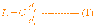
It is well known that a good quality resistor should be low noise, the ohmic value should remain stable over time and over a range of temperatures, the stated value should closely match the actual value and inductive and capacitive parameters should be negligible at audio frequencies. Its prime purpose according to Ohm's law, is to drop voltage, or looked at another way, limit current. It should do this regardless of how fast the current/voltage changes. Modern metal or carbon film resistors do this admirably across the audio range and well beyond. A common garden 1% metal film 1/2 watt resistor of superb performance costs about around 2p each! A typical 'audio quality' resistor ,sometimes not even a 1% device, costs several factors of ten more, but offers absolutely nothing audibly or electrically useful compared to our humble 2p resistor! 'Audio' capacitors are another strange recent addition to the standard family of capacitors found on component suppliers lists. All good electronic engineers know that certain types of capacitor offer a better performance in certain applications than another. A perfect capacitor should behave such that the instantaneous current through the capacitor (ic) is directly proportional to the rate of change of voltage (dv/dt) across its plates , the value of the capacitor (C) being a constant. In mathematical terms; This should ideally apply at all temperatures and at any rate of change of voltage. Unfortunately other parameters exist on a real capacitor that mars this relationship. Series resistance, leakage resistance, inductance, value stability with temperature and frequency, all play their part in destroying the ideal current/voltage relationship. At radio frequencies the capacitor type used is crucial for the circuit to function at all. In audio circuitry, a poorly chosen capacitor type may effect the performance to a degree. Amplifier design engineers (ADEs) know what types not to use for certain applications. Even if cost is a major consideration, they will not use a wrong type if there is a chance it will mar the sound. For example, instead of using a polyester/polypropylene film capacitor for coupling two circuits, cost say 30 pence, a 5 pence tantalum or electrolytic type might be used instead. It is well known by ADEs that the latter types are not as good as foill types electrically and can add a tiny amount of distortion. The crucial questions are 1/'how much?' and 2/ 'is it at all audible?. In a well designed amplifier where the capacitor types are chosen sensibly, the answers are, 1/'an insignificantly small amount' and 2/ 'no, its well below the noise floor". Why is this the case? To illustrate this, lets follow the signal on it's path from the CD player through to the loudspeaker system, and ultimately to the human aural system. We will assume a reasonably respectable amplifier with less than 0,01% total harmonic and less than 0.01% intermodulation distortion. The voltage level of the audio signal from the CD player appears at the input leg of the first capacitor in the amplifier chain as several hundred millivolts rms. Lets say, 440mV r.m.s., the old domestic line level. (Nowadays its usually a lot higher at around 2V r.m.s.) This originated in a recording studio from electrical signals fed to a mixer desk via a set of microphones. Already the signal has passed through scores of capacitors. The composite signal is recorded onto a master tape or disc and then stamped onto your CD as a series of miniscule digitally encoded bumps and troughs. The undulations are read by a laser and converted from digital form to a varying signal voltage inside the CD player. Again passing through several capacitors as it does so. The signal then passes through the interconnecting cable to the amplifier itself. At the input of the amplifier, the harmonic and intermodulation distortion level in the source music is well above the distortion and background noise level of the amplifier. Now let us consider the distortion caused by a 'non-audiophile quality, capacitor' in the signal chain. The level of the capacitor distortion components relative to the source distortion is hundreds of times lower. In fact, in our decent amplifier, it is well below the noise floor. You couldn't possibly hear it. Looked at another way. If the total harmonic distortion in the signal is 2% (a very conservative figure) and the total harmonic distortion (THD) of the amplifier is a mere 0.01%, (which includes the much lower distortions from the capacitor), it doesn't take a genius to see that mucking about changing capacitors for the sake of it, won't make any audible difference. Now let's follow the signal out of the amplifier:.
For ure listening pleasure